

Every manufacturability check, in one place
OptiQC runs these checks on the real B-rep geometry of your STEP model, deterministically, and highlights each finding on the exact face, edge, or bore. Thresholds are tunable per process.
How findings are shown
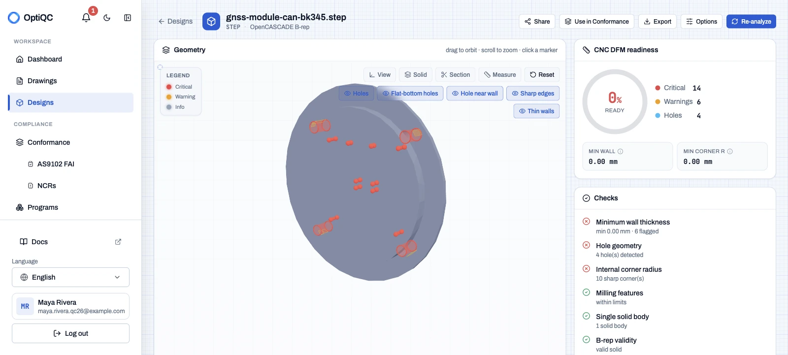
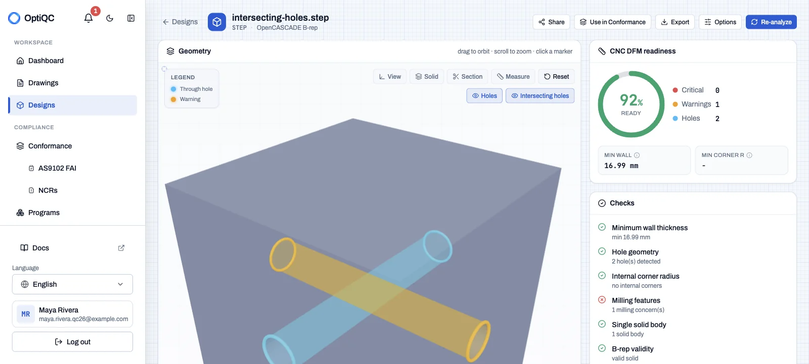
Every finding is drawn directly on the geometry, never as a floating marker, so you can see exactly what to fix.
CNC milling18 checks
Prismatic parts cut on 3 to 5 axis mills. Watch tool reach, wall and floor thickness, hole geometry, and sharp internal corners.
Thin wall
WarningWall too thin to machine without deflection or breakthrough.
Thin floor
WarningPocket or feature floor too thin to machine safely.
Sharp internal corner
CriticalRe-entrant inside corner with no radius; a round tool physically cannot reach it.
Small radius
InfoInside fillet smaller than the smallest available end mill.
Pocket corner radius
InfoVertical pocket corner rounded tighter than the tool radius.
Floor fillet
InfoFloor-to-wall fillet that forces a ball or bull-nose cutter and slow finishing.
Small hole
WarningBore below the smallest practical drill diameter.
Deep hole
WarningDepth-to-diameter ratio that makes drills wander or snap.
Flat bottom hole
InfoBlind hole with a flat floor that needs a flat drill or end mill.
Hole near wall
WarningThin remaining ligament between the bore and the nearest solid wall.
Deep pocket
WarningDepth-to-width that needs long, chatter-prone tooling.
Narrow slot
WarningSlot so narrow it needs a fragile, easily broken cutter.
Tall thin rib
WarningStanding wall so slender it deflects and chatters.
Angled hole
WarningHole axis off the spindle axis; needs an angled fixture or 5-axis.
Non-standard hole
InfoDiameter is not a standard drill size; needs reaming, boring, or a special tool.
Intersecting holes
WarningCrossing bores deflect or break the drill where they meet.
Knife edge
WarningA thin, fragile wedge of material that chips during machining.
Undercut
WarningFeature unreachable from the available tool axes.
CNC turning6 checks
Revolved parts on a lathe. Watch slenderness, deep bores, narrow grooves, and features that need live tooling.
Thin wall
WarningWall too thin to machine without deflection or breakthrough.
Slender part
WarningLong, thin part that whips and deflects between centers.
Deep bore
WarningDeep internal bore where the boring bar deflects and chatters.
Narrow groove
WarningGroove that needs a thin, fragile parting or grooving blade.
Non-round feature
WarningFlats or cross-holes that turning alone cannot make (needs milling or live tooling).
Sharp shoulder corner
WarningInternal shoulder corner that needs a tool-nose radius and cannot be dead sharp.
Injection molding4 checks
Molded plastic parts. Watch wall thickness, uniformity, and draft so parts fill, cool, and release cleanly.
Thin wall
WarningWall too thin to machine without deflection or breakthrough.
Thick section
WarningHeavy wall causes sink marks, voids, and long cycle times.
Non-uniform wall
WarningUneven wall thickness warps the part as it cools.
Insufficient draft
WarningWalls too vertical to release from the mold cleanly.
Sheet metal4 checks
Bent and cut sheet parts. Watch gauge consistency, bend radius, flange length, and holes near bends.
Non-uniform thickness
WarningPart is not a single consistent sheet gauge.
Bend radius too small
WarningInside bend radius so tight the material cracks.
Flange too short
WarningFlange too short to grip and form on a press brake.
Hole near bend
WarningHole too close to a bend; it distorts when the part is formed.
Model quality4 checks
Checks on the file itself: valid topology, a single solid, and no sliver faces or short edges that break CAM.
Invalid topology
CriticalBroken topology the CAD kernel cannot validate (bad faces, self-intersections, non-watertight solid).
Multiple solids
WarningThe file contains more than one disconnected solid body.
Sliver face
WarningA near-zero-area face, usually a translation or modeling artifact.
Short edge
WarningA near-zero-length edge that can break downstream CAM.
Every threshold is configurable
Set minimum wall, tool radius, hole limits, draft, and bend rules per process at the organization level, or override them on a single model.
What is a DFM check?
A DFM (Design for Manufacturability) check is an automated rule that tests part geometry against the limits of a specific manufacturing process. Each check compares a measured feature - wall thickness, internal corner radius, hole depth-to-diameter ratio, slot width, draft angle, or bend relief - against a configurable threshold, and flags the feature when it falls outside what the process can produce reliably. OptiQC evaluates these rules deterministically on the real B-rep geometry of your STEP model, not on screenshots or guesses, so results are repeatable and explainable. Findings are drawn on the exact face, edge, or bore they refer to and graded by severity, letting engineers fix manufacturability problems before a quote or a production run rather than discovering them on the shop floor.
Catch manufacturability issues before production
Upload a STEP file and get a scored, explainable DFM report in minutes.